Decoding Cold Shrink Cable Terminations - Exploring their Features and Applications
Introduction
Cold shrink cable terminal
The early cold-shrinkable cable terminals only used silicone rubber cold-shrinkable components for additional insulation, and the electric field treatment still used stress cone type or stress tape wrapping type.
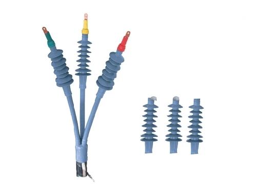
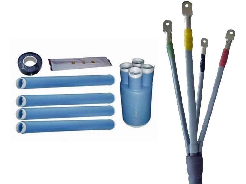
Cold shrinkage stress control tubes are now commonly used, with voltage levels ranging from 10kV to 35kV. Cold-shrinkable cable terminals use cold-shrink insulating tubes for reinforced insulation at the 1kV level, and cold-shrinkable insulation parts with internal and external semi-conductive shielding layers at the 10kV level. The three-core cable terminal bifurcation adopts cold shrink branch sleeve.
Cold shrink cable terminals have the advantages of small size, easy and rapid operation, no need for special tools, wide application range and few product specifications. Compared with heat-shrinkable cable accessories, it does not need to be heated with fire, and moving or bending after installation does not cause the risk of detachment of the internal layers of the accessory like heat-shrinkable cable accessories (because the cold-shrinkable cable terminal head is pressed by elastic tightness). with prefabricated
Compared with the prefabricated cable accessories, although they rely on elastic compression force to ensure the internal interface characteristics, they do not correspond to the cable cross-section one-to-one like the prefabricated cable accessories and have many specifications.
It must be pointed out that before being installed on the cable, the components of the prefabricated cable accessories have no tension, while the cold-shrinkable cable terminals are under high tension. Therefore, it must be ensured that the cold-shrinkable components should not be stretched during the storage period. There is obvious permanent deformation or elastic stress relaxation, otherwise sufficient elastic pressing force cannot be guaranteed after installation on the cable, and thus good interface characteristics cannot be guaranteed.
Instructions for use
The following is an introduction to the structure, installation process and precautions of 10kv and 35kv cold shrink cable terminals and 10kv cold shrink cable terminals.
1. 10kv three-core cable cold shrink cable terminal
(1) Peel off the cable outer sheath, steel strip (if there is a steel strip), inner sheath and wire core filler according to the dimensions specified in the installation instructions provided by the manufacturer (the stripping length of the steel strip is mainly determined by the allowable bending radius of the wire core) and the specified distance between phases, but it must be considered to be compatible with the length of the cold shrink sheathing tube provided on the wire core). Leave 10mm for the inner sheath and 25mm for the steel strip. Then scrub the outer sheath of about 50mm long at the end of the cable.
(2) Install the ground wire. Install grounding copper rings on the core copper shielding about 65mm above the steel strip, and use constant force springs to fix the grounding braided copper wire and the three copper strips together on the steel strip. If the steel strip and wire core shielding are required to be grounded separately, another 10mm2 braided copper wire should be fixed on the steel strip with a constant force spring, then wrapped and covered with insulating tape, and then the wire core shield should be grounded with the braided copper wire and the three wire cores. Grounded copper tape connection lead out.
Note: There must be no electrical connection between the steel strip grounding wire and the wire core shielding grounding wire in the terminal head. In order to prevent water vapor from entering the cable along the ground wire, first wrap 2 layers of waterproof tape on the outer sheath, sandwich the ground wire in the middle, and then wrap 2 layers of waterproof tape on the outside.
(3) Install cold shrink branch sleeves. Place the cold shrink branch sleeve at the bifurcation of the wire core, first pull out the plastic spiral strip inside the lower end, then pull out the plastic spiral strips inside the three tubes, and shrink and tighten it at the bifurcation of the wire core.
(4) Install cold shrink sheathing tube. Put the three cold shrinkable sheathing tubes on the three wire cores respectively, and cover the branch casing finger tubes 15mm below. Pull out the plastic spiral strip in the tube, shrink and tighten it on the copper shield of the wire core. If it is an extended indoor terminal head, use the same method to shrink the second cold shrink sheathing tube, and its lower end overlaps the first one by 15mm. The length from the end of the sheathing tube to the end of the wire core should be equal to the size specified in the installation instructions.
(5) Leave a section of copper shield upward from the sheath pipe mouth (leave 45mm for the outdoor terminal head and 30mm for the indoor terminal head), and peel off the rest.
Leave 10mm of semi-conductive layer, peel off the rest of the semi-conductive layer, and add 10mm to the depth of the terminal hole to peel off the insulation at the end of the wire core.
(6) Start wrapping the semi-conductive tape 10mm from the end of the steel shielding tape until it covers 10mm of the cable insulation, and then return to the copper shielding tape. It is required that there is a smooth transition between the semi-conductive tape and the insulation (no obvious steps).
(7) Crimp terminals.
(8) Install cold shrink insulation parts. First use cleaning agent to clean the cable insulation and terminals at the crimped joint. And apply a little silicone grease on the surrounding semiconductive tape and nearby insulating surfaces. Insert the cold shrink insulation piece to the position specified in the installation instructions, pull out the plastic spiral strip, and shrink it on the cable insulation (if the width of the terminal block is larger than the inner diameter of the cold shrink insulation piece, the cold shrink insulation piece should be installed first, and then crimp terminals).
(9) Use insulating rubber tape to wrap the gap between the terminal and the core insulation, and then wrap it with anti-leakage tape.
(10) Wrap the phase-colored marking tape around the outer sleeve of the three-phase core branch sleeve.
2.35kv single core cable terminal
The structure and process of the 10kv three-core cable terminal are simpler than that of the 10kv three-core cable terminal. There is no need to install branch sleeves and sheathing tubes on the wire cores. The rest are basically the same as the three-core cable terminal.
3. 10kv three-core cable connector
The installation process is similar to that of prefabricated joints, but the following differences should be noted:
(1) When placing the main body of the cold shrink joint on the stripped and cut longer end of the cable core, the tap of the plastic spiral strip should face the bifurcation of the cable core at that end.
(2) After all relevant components are placed on the cable core, the cable conductors and crimping tubes at both ends do not need to be crimped twice like prefabricated joints.
(3) Before moving the main body of the cold shrink joint to the middle of the joint, apply the special mixture provided by the manufacturer evenly on the interface between the semiconductive layer and the insulation and on the insulation surface.
(4) Install shielded copper mesh bridge wires and steel strip jumpers, usually fixed with constant force springs.
(5) The cold shrink joint is wrapped with a layer of waterproof tape with a half-cover, covering both ends of the cable outer sheath by 60mm, and then armored tape is used to wrap the entire joint surface. After curing, it has good mechanical protection. This armorcast is a pre-impregnated curable black polyurethane fiberglass braided tape, vacuum packed. Open the package before use, fill with water for 15 seconds, pour out the water, and you can use it. Other suitable protective layers or boxes may also be used.
Model cable accessories
Molded cable accessories are mainly used on straight-through joints of cross-linked cables of 35kv and above. It uses radiation cross-linked or chemical cross-linked polyethylene film tape to wrap around the treated cable joint, press it with the help of a special mold (aluminum mold or heat-resistant tension tape), and heat to form the joint. During the production process, the radiation cross-linked polyethylene tape is pre-stretched (stretched by 30% at 100c, then cooled and cut into rolls), wrapped into joints, and then heated and retracted to make the wrapped tape The air gap between layers is compressed, which has the effect of increasing the discharge voltage of the air gap. This kind of joint has a high level of partial discharge and is suitable for making cable joints with higher voltage levels. Due to the long wrapping and heating time, this type of joint is generally not used for cables below 35kv. Even for 35kv cable joints, because the wrapping and prefabricated joint processes are more convenient, molded joints are not used much.
The 35kv cable molded joint is wrapped on site. Therefore, in addition to requiring the operator to strictly follow the dimensions and requirements specified in the drawing, it is also related to the environmental conditions during construction such as (humidity, dust, etc.). The humidity should not be too high. There should be a rainproof and dustproof tent at the construction site, and rubber gloves should be worn when wrapping the bag.
Cast cable accessories
The materials used in cast cable accessories include epoxy resin, polyurethane and acrylate. Polyurethane is mostly used in extruded insulated cables and is mainly used as straight-through joints and branch joints. Cured polyurethane has high elasticity, and its expansion coefficient is also relatively close to that of extruded cable insulation materials, which is very beneficial to improving the interface properties of cable insulation and reinforced insulation in the joint. Polyurethane and polyurethane have strong binding force, so its advantages are even more obvious when used as polyurethane insulated cable joints.
The structure and installation process of cast cable joints have certain differences among manufacturers, but the cable stripping and cutting process and operating points are basically the same as other cable joints. There are two ways to deal with the electric field at the cutoff point of the cable's outer semi-conductive shielding layer: one is to wrap a stress control tape there; the other is to wrap a stress cone.
For 35kv cable joints, ethylene propylene rubber self-adhesive tape is generally wrapped around the cable insulation surface as a transition layer. The connector shell is usually provided by the factory, and the metal shielding layer inside the shell should be reliably connected to the cable shielding layers at both ends.
If mold casting is used, semi-conductive self-adhesive tape should be used to wrap the insulating surface of the joint after demoulding, and then a shielding copper mesh should be applied. The copper mesh should be reliably connected to the cable shielding layers at both ends. Then, install the joint bridge wire and the outer protective layer of the joint (usually heat shrinkable sheathing tube).
The correct operation of the pouring process has a great impact on the performance of the cable accessories, so special attention should be paid. First, check whether the casting agent used has exceeded the storage period (instructions on the packaging). Before pouring, the two components of the casting agent should be fully stirred evenly, and then pour slowly from pouring to l to avoid the occurrence of bubbles.
There are three main levels of applicable standards for cable accessories:
First layer: IEC standard
IEC62076 "Power cable systems for extruded insulated power cables and accessories with rated voltages from 150kV (Um=170kV) to 500kV (Um=550kV) - Test methods and requirements"
IEC60840 "Test methods and requirements for extruded insulated power cables and accessories with rated voltages from 30kV (Um=36kV) to 150kV (Um=170kV)"
IEC60859 "Cable connection device for gas-insulated metal-enclosed switches with rated voltage 72.5kV and above"
IEC60502 "Extruded insulated power cables and accessories with rated voltage above 1kV (Um=1.2kV) to 30kV (Um=36kV)"
IEC60055 "Paper insulated metal sheath with rated voltage 18/30kV and below (with copper or aluminum body, but excluding compressed air and oil-filled cables)" Part 1 "Cable and Accessories Test" Chapter 7: Type Test of Accessories
IEC61442 "Test method for power cable accessories with rated voltage 6kV (Um=7.2kV) to 30kV (Um=36kV)"
Second level: national standards (GB standards)
GB/Z18890 "Rated voltage 220kV (Um=250kV) cross-linked polyethylene insulated power cables and accessories"
GB/Z11017 "Rated voltage 110kV cross-linked polyethylene insulated power cable and its accessories"
GB5589 "Cable Accessories Test Methods"
GB9327 "Test methods for cable conductor compression and mechanical connection joints"
GB14315 "Crimping type copper and aluminum terminal blocks and connecting tubes for conductors of wires and cables"
Note: GB11033 "Basic Technical Requirements for Power Cable Accessories with Rated Voltage 26, 35kV and Below" has been decentralized to JB/T8144
The third level: industry standards
JB standard (Machinery Industry Association standard)
JB/T8144 "Basic technical requirements for power cable accessories with rated voltage 26/35kV and below" original GB11033
JB6464 "Straight-through wrap-around joint for power cables with rated voltage 26/35kV and below"
JB6465 "Indoor and outdoor porcelain sleeves for power cables with rated voltage 26/35kV and below are terminals"
JB6466 "Indoor and outdoor porcelain sleeve terminals for power cables with rated voltage 8.7/10kV and below"
JB6468 "Indoor and outdoor wrapped terminals for power cables with rated voltage 26/35kV and below"
JB7829 "Indoor and outdoor heat shrinkable terminals for power cables with rated voltage 26/35kV and below"
JB7830 "Straight-through heat shrinkable joint for power cables with rated voltage 26/35kV and below"
JB7831 "Indoor and outdoor cast-type terminals for power cables with rated voltage 8.7/10kV and below"
JB7832 "Straight-through pouring joint for power cables with rated voltage 8.7/10kV and below"
JB/T8501.1 "Indoor and outdoor prefabricated terminals for plastic insulated power cables with rated voltage 26/35kV and below"
JB/T8503.2 "Indoor and outdoor prefabricated terminals for plastic insulated power cables with rated voltage 26/35kV and below"
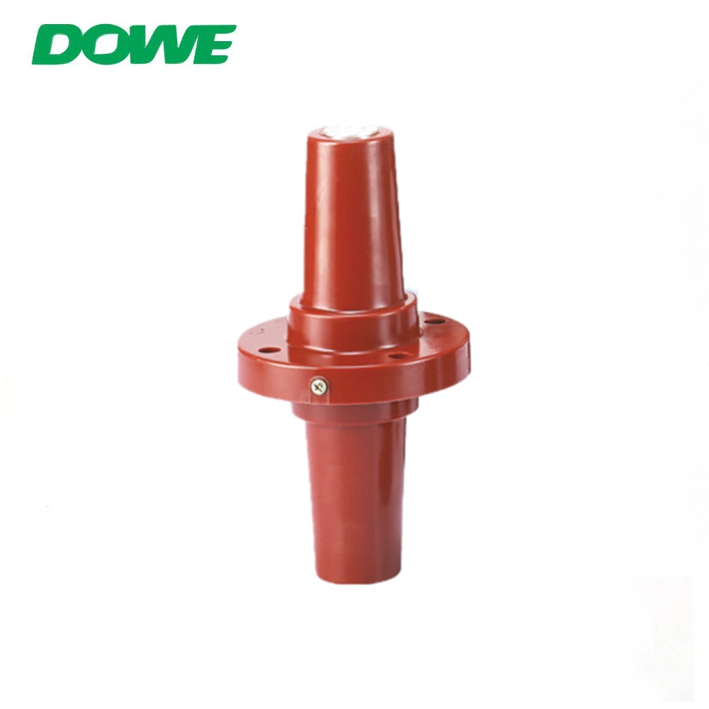
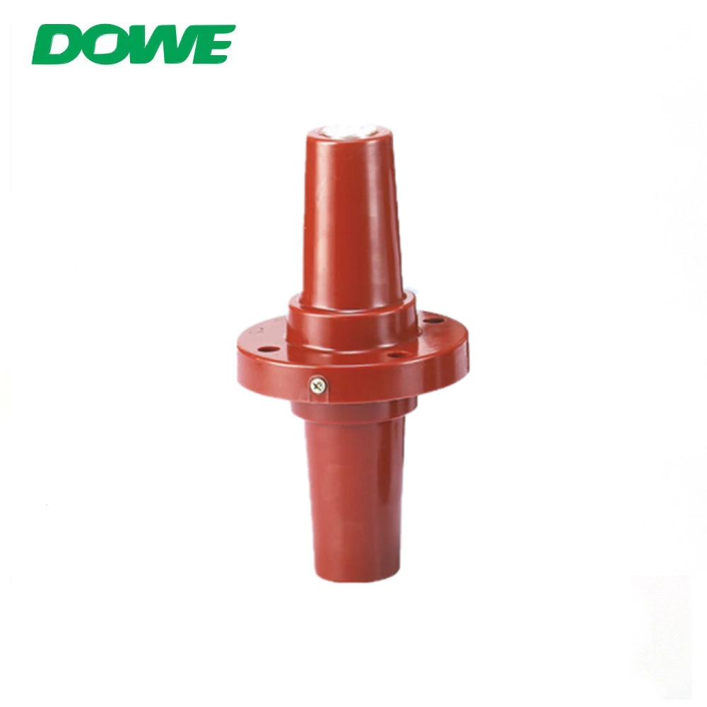
Related Products: Cold Shrink Cable Termination Accessories
